| Range of Application | Monitoring Modes | Counting | Conclusion |
| Download TMG-1200 PDF |
Non-Contact Fault Detecting
 Monitoring high-speed headers while running helps ensure quality parts by sending a fault signal to stop the machine when the variation of the ran position exceeds a preset range.
Achieving quality fastners takes more than inspecting the pieces after thay have been produced. Over the years we have seen an increased interest in techniques to monitor the process and stop the machines as soon as there is a deviation from the expected action.
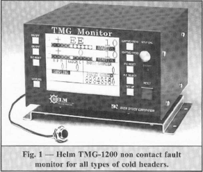
Our latest development for process quality control is the TMG-1200 Monitor, Figure 1. This instrument detects, using a proximity sensor, the Front Dead Center (FDC) position of the ram on the machine. If an abnormal condition, such as a short or long misfeed; cracked or broken inserts, dies and punch assemblies; fractured or rotated transfer fingers; double hits or dropped slugs happens, it will cause this ram position to deviate on the very stroke. This will detect a fault whose output signal will cause the machine to shut down.
This concept very accurately measures the separation gap at the proximity sensor (within 0.001mm or 0.0004″) where a previous method was a load monitoring system.
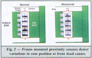
That system put a transducer within the force footprint of ech die, a time consuming installation practice. Our sensor mounted on the frame and the sensor target mounted on the ram, Figure 2. This is a relatively simple installation. An abnormal condition that effects the FDC with produce a fault signal.
Because this instrument senses the separation gap with every stroke of the machine, (up to 1200 spm) it is able to also monitor the speed of the machine. It displays the value in real time. When the slowdown detection feature is set to the ON position, the unit will send a fault signal to the output when the rpm falls below a preset range.
Slowdown is a result of machine monitor overload and represents a fault to be corrected. Slowdown protection can be set in incremental units of 1% in the range of -5% to -49%.

A single monitor have two output displays and can monitor in either a single or double mode configuration. The single mode is for single stroke, single die machines. For these applications, the screen display is limited to on channel only. The double mode is for single stroke, double die machines (such machines that perform work with two punches acting in one stroke). In this case detection is made for two punches at the same time using one sensor without requiring external timing. A multi-mose is for multiple slide or progressive headers. Detection is performed using two sensors. With on each installed at the left and right sides of the slide, fault detection is made based on the inclination of the slide. Applications of this technology also include boltmakers and nutformers.
|
|
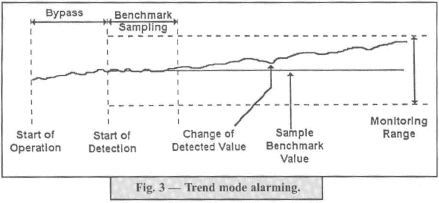
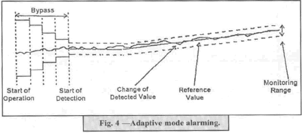
To fully understand the simplicity, yet flexibility of this instrument it helps to review the ways in which the detected values are displayed. The choices on the monitor display panel are either Trend or Adaptive. The device is capable of performing trend value detection and adaptive value detection. These detection modes are performed at the same time.

|
|
Just as the detection of each stroke enable the meaurement of the speed of the machine, that feature can also be utilized to provide counting of the production runs. Three counter displays show on the face of the monitor.
|
|
Monitoring cold heading type machines has been made simpler with an instrument that is simple to install and to use. This protects the tooling and the machine makes fewer rejected parts.
|


